|
Douglas XO-14, 28-194 (Source: Klein)
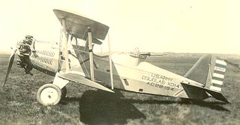 |
At right and below is Douglas XO-14, 28-194. This airplane
landed at Tucson somewhere during the third week of July,
1930. It was flown by MSgt. J.L. Waugh. His passenger was
SSgt. George Goodrich.
Interestingly we have many images of this airplane (see below), but not
a lot of information about the pilot or the history of the
aircraft. The locations of these first two images are unknown.
Douglas XO-14, 28-194, Location Unknown (Source: Klein)
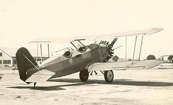 |
Note the change in rear cockpit configuration
between the top and the image to the right. In the second image, it
appears that the gunner's machine gun mount and built-up cockpit wall was removed and
a standard passenger cockpit was installed. It is not clear
if the airplane in the second image was still on the military
roster. Perhaps it was and was converted to a military hack,
or surveyed and turned into a civil airplane. See below.
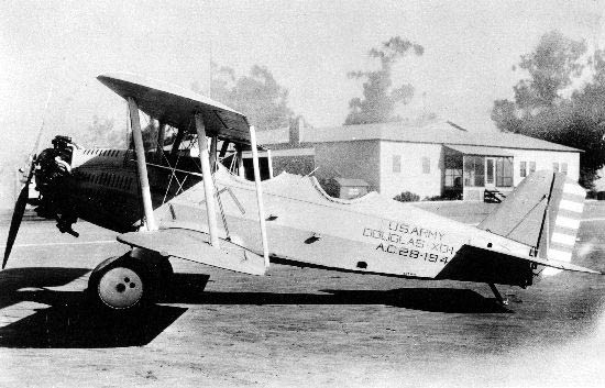
Below, courtesy of the San Diego Aerospace Museum (SDAM), is another left profile view of the airplane.
Douglas XO-14, 28-194, Location Unknown (Source: SDAM)
 |
---o0o---
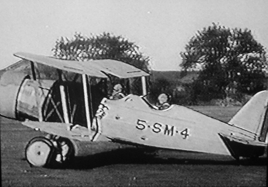
A site visitor from France, Christian Santoir, states, "This plane can be seen in the RKO movie "The Marines Fly High" (1940) with Richard Dix and Chester Morris.... In the film it is a US Marine observation plane with a fake code : '5 SM 4'." The following two images show the airplane in frames provided by Mr. Santoir from that movie. He asks us to note that the airplane is equipped with a NACA cowling in its movie role. And the rear cockpit is as discussed above.
Douglas 28-194 In "The Marines Fly High" (1940) (Source: Santoir)
 |
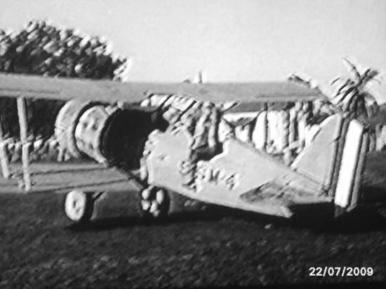
Mr. Santoir sources and maintains a Web site, www.aeromovies.fr. His expressed purpose is to, "...comment on [aviation] movies, describing and tracking (when it is possible) every plane seen on the screen (with c/n, s/n, registration, the owner, where it comes from, what it becomes, and so on).... I have 673 movies in my library and 386 (from 1913 to present, with movies from USA, Germany, Korea, Japan, Sweden, URSS, Italy)." A labor of love including, soon, a page about "The Marines Fly High". You would do well to fire up your Google translator and give his site a good browse. The specific page dedicated to "The Marines Fly High" is at the link (PDF 23Kb), roughly translated from the French.
Douglas 28-194 In "The Marines Fly High" (1940) (Source: Santoir)
 |
Further, he states, "According to aerofiles.com and R.J. Francillon 'McDonnell-Douglas Aircraft Since 1920', there has been only ONE XO-14 built (c/n 477). It had first a civil reg. number NX13753 before being delivered to USAAC in February 1929 with serial 28-194. It remained in service at Wright Field (XP539) until July 1933. Then, it was sold to a private owner." Thus, the rear cockpit configuration shown in the second image from the top of the page could have been on the airplane either before February, 1929, or after it was in the military (post-1933).
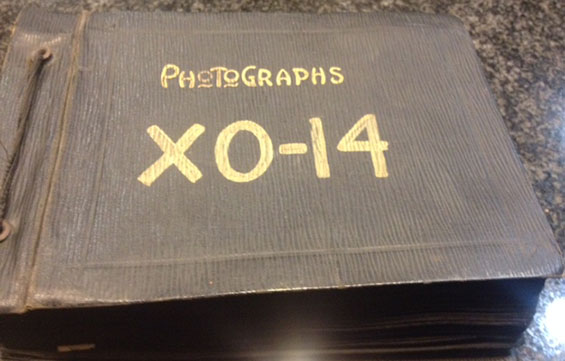
What follows is an outstanding and unusual set of photographs shared by site visitor Ben Browne. Mr. Browne owns a photo album, which documents the original construction of 28-194/NX13753/SP539. The cover of the album is below.
Douglas 28-194 Photo Album (Source: Browne)
 |
The entire album appears as follows.
Douglas 28-194 Photo Album (Source: Browne)
 |
Mr. Browne disassembled the album for us and provides the following scans of the 64 individual pages. These are beautiful images of a one-of-a-kind airplane. Kudos and thanks to Mr. Browne for taking the time and making the effort to share them, and kudos to Douglas for documenting the construction so that we can view the intimate details of this airplane now, almost 90 years after these photographs were taken.
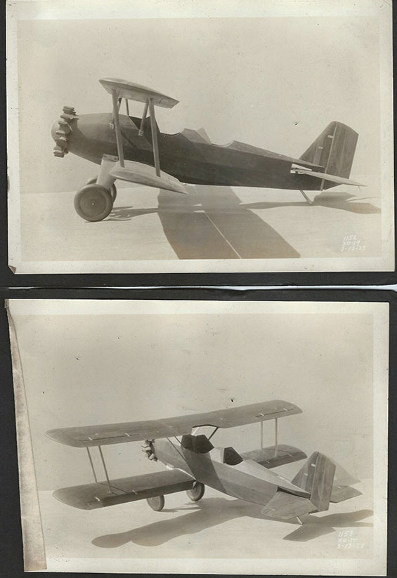
These first two photographs appear to be a model of the airplane. These photos were taken on March 13, 1928.
Douglas XO-14, Album Pages 1-2 (Source: Browne)
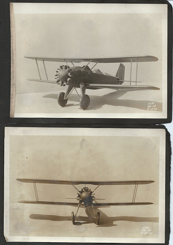 |
Pages 3-4 are also photos of the model. These shots were also taken March 13, 1928. The model appears to be crafted from solid wood.
Douglas XO-14, Album Pages 3-4 (Source: Browne)
 |
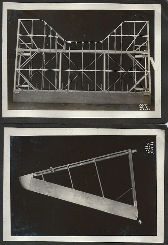
Pages 5-6 include a final model photo (snapped March 13th), and the starboard half of the horizontal stabilizer (snapped on August 17, 1928). The twisted inter-rib braces in this photograph appear to be thin metal strips riveted to the ribs. Usually inter-rib bracing material is a woven cloth tape.
Douglas XO-14, Album Pages 5-6 (Source: Browne)
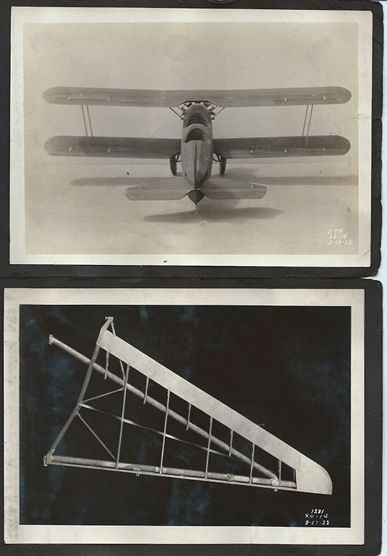 |
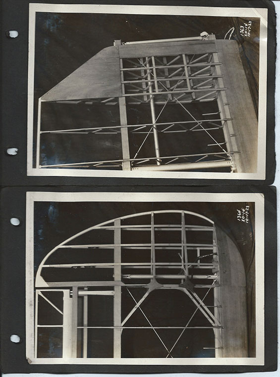
Pages 7-8, photographed August 17, 1928, exhibit the internal structure of the port horizontal stabilizer (top image). There is a fitting on the top about a third of the way from the tip that would anchor a support cable to the vertical stabilizer. See images of the completed aircraft, below, to better understand this geometry. The bottom image appears to be the rudder with three hinge posts. The vertical stabilizer, to which the rudder would be attached, is pictured a few photos down.
Douglas XO-14, Album Pages 7-8 (Source: Browne)
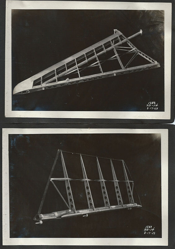 |
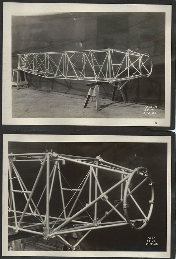
Pages 9-10 include another image of the rudder at top, and a starboard view of the fuselage. These photos were snapped August 17-18, 1928.
Douglas XO-14, Album Pages 9-10 (Source: Browne)
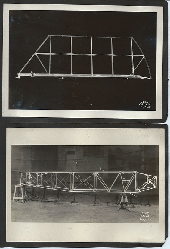 |
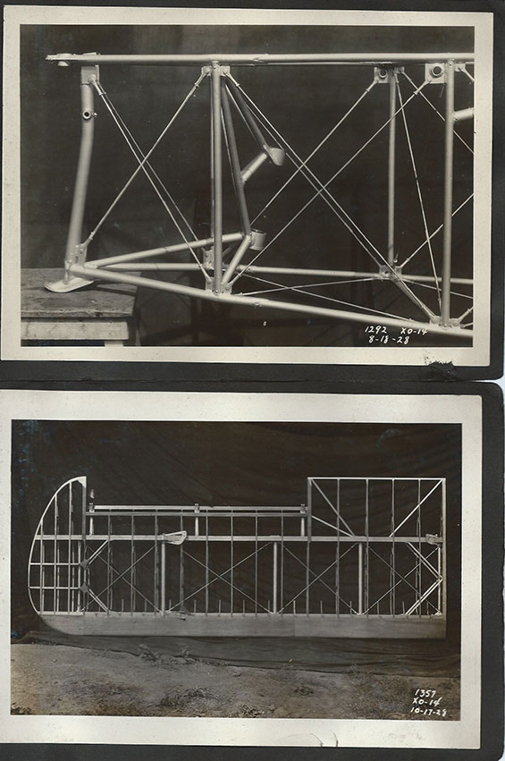
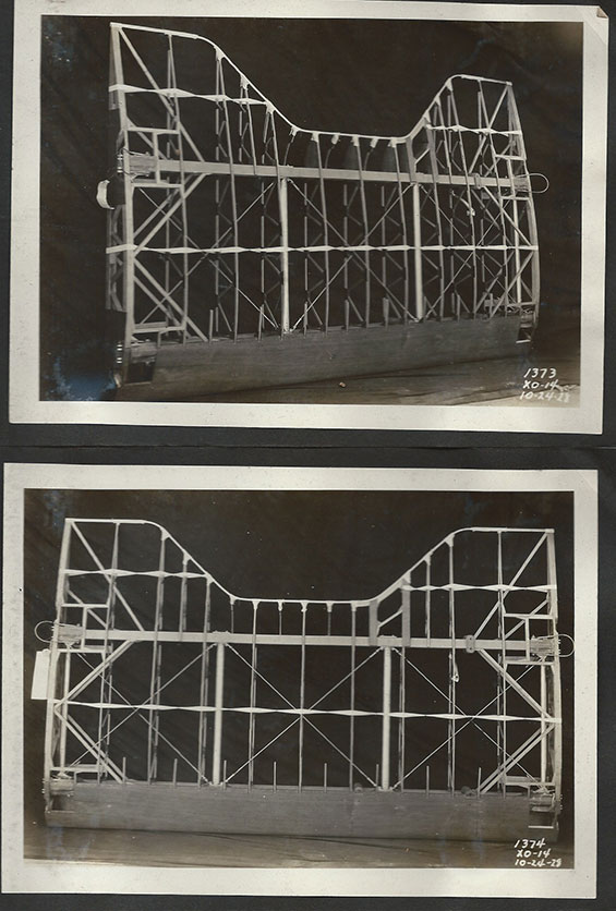
Pages 11-12 show two starboard oblique views of the fuselage structure. This was a robust airplane. These images were taken August 18, 1928.
Douglas XO-14, Album Pages 11-12 (Source: Browne)
 |
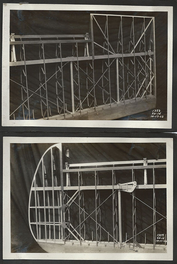
Below, pages 13-14 show details of the rear fuselage (top) and port, upper wing, snapped August 18 and October 17, 1928, respectively.
Douglas XO-14, Album Pages 13-14 (Source: Browne)
 |
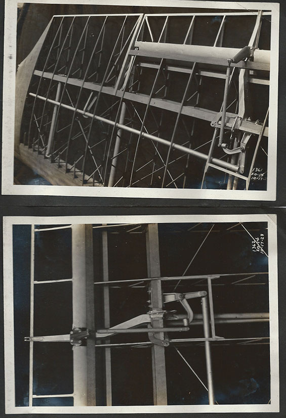
Below, two more views of the top, port wing, snapped October 17, 1928. The aileron hinge attachments are clearly visible.
Douglas XO-14, Album Pages 15-16 (Source: Browne)
 |
Below, two topside views of the lower port wing with the aileron push tube installed and the aileron bellcrank attached to the rear wing spar. The aileron is installed and is attached by another short push tube to the bellcrank. This wing attaches to the fuselage at the left side of the photo. The push tube traverses the interior of the wing from the control stick in the cockpit to the bellcrank shown at the lower right of the photo.
Follow along: the control stick is pushed left by the pilot in a manner that institutes a left bank. The lower angle of the aileron bellcrank is pushed to the right. The upper arm of the bellcrank pulls the short push tube down, thus raising the aileron from its neutral position as shown. This makes the left wing go down, thus beginning the left turn. The lower photo illustrates how the upper arm of the aileron bellcrank is bent at a right angle in order to transfer the control stick forces from lateral to longitudinal.
Notice in the lower photo the small fitting at the trailing edge of the aileron. To this fitting was attached a control arm to the upper aileron so that when the lower aileron was activated, the upper would passively slave to the same angle through the control arm. You can see this control arm between the lower and upper ailerons in the three photos at the top and bottom of this page (q.v). Look closely and you can see the short push tube where it exits the interior of the wing and attaches to the aileron. These photographs were made on October 17, 1928.
Douglas XO-14, Album Pages 17-18 (Source: Browne)
 |
Below, two more images of the lower port wing taken on October 17, 1928. The top image shows the bottom of the wing where it attaches to the fuselage. Notice the closely spaced half-ribs and extra reinforcements near the fuselage. This would allow for the weight-bearing wing walk, which would support the weight of the pilot and crew as they entered and exited their cockpits. The aileron push tube is also visible.
The bottom photo illustrates nicely the wing bow that defines the tip of the wing (this bow fashioned of steel tube). The leading edges of the wing, the wing walk, and the nicely formed gussets in the lower photo are fashioned of mahogany plywood, a structural material still in use in modern "ragwing" aircraft. Look carefully at the lower photo and you can see electrical leads near the wingtip. These leads supplied wingtip running lights that you can see in the third photo from the top of the page. I'll point out, too, that pages 19-20, below, are shown as I received them from Mr. Browne. The photos are mounted on typical black album paper and double-hole punched. I trimmed the rest of the images so that details would be larger.
Douglas XO-14, Album Pages 19-20 (Source: Browne)
 |
Below, pages 21-22 illustrate the top wing center section. The wing attach points are visible as the hardware bolted to the front and rear spars. Four cable loops extend from the top of the rear spar as lift points during assembly. The tag at the left side identifies the part.
Douglas XO-14, Album Pages 21-22 (Source: Browne)
 |
Pages 23-24 illustrate the bottom of the wing center section, and the vertical stabilizer (see above).
Douglas XO-14, Album Pages 23-24 (Source: Browne)
 |
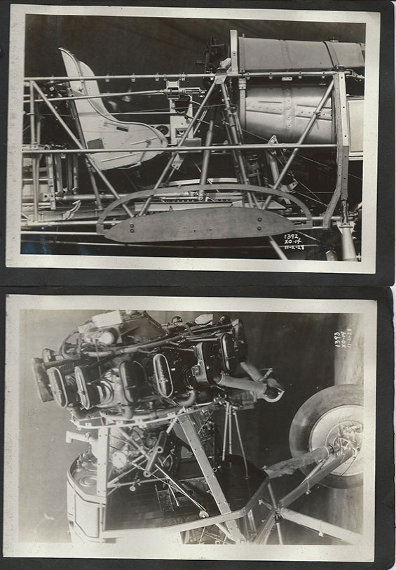
Pages 25-26, below, illustrate the rear cockpit, which was populated with radio equipment. The top photo shows a reel-like structure at the occupant's left knee. This was a reel of wire for the radio antenna. A Morse Code key is visible at left center. The antenna reel, with handle, is more easily seen in the lower photograph. Note, too, the built-up cockpit sides and the turtle deck for the radio operator/gunner cockpit. The fuselage is on wheels now, which you can see at the top corners of the bottom photo.
Douglas XO-14, Album Pages 25-26 (Source: Browne)
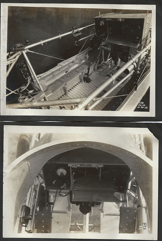 |
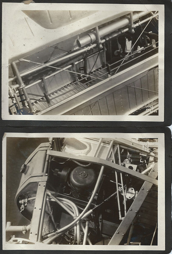
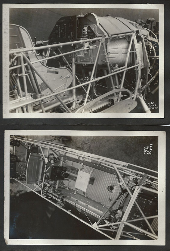
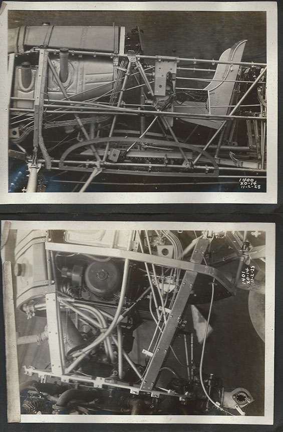
From October 30, 1928, the photographs below show some of the details of wire and tube routing in the starboard fuselage wall (top photo). The built-up cockpit sides are visible at the top of this view. In the bottom view, details of the engine compartment. In the lower photograph (turned 90° CCW), forward is to the left.
Douglas XO-14, Album Pages 27-28 (Source: Browne)
 |
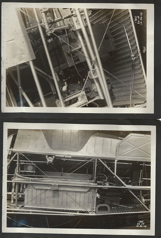
The two photos, below, show details of the rear cockpit from starboard (top) and port sides. Note in the port view at bottom the step built in to the fuselage to ease the job of getting in and out. The rear cockpit built-up cockpit wall is seen to advantage in the bottom photo, as is the equipment access door hinged upward behind the cockpit.
Douglas XO-14, Album Pages 29-30 (Source: Browne)
 |
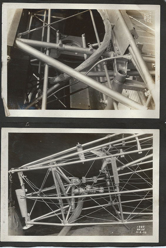
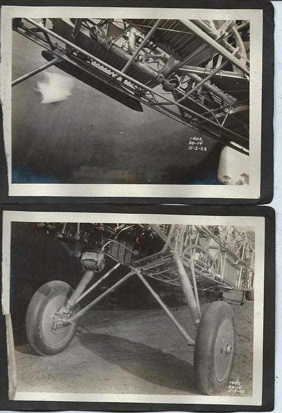
Below, details of the rear cockpit photographed October 30, 1928 (top). At bottom (November 2, 1928) are details of the tail skid and the myriad of control and reinforcement cables and pulleys. The curved, vertical tail skid appears to be damped with a robust coil spring.
Douglas XO-14, Album Pages 31-32 (Source: Browne)
 |
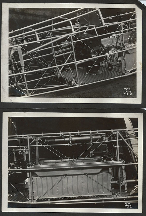
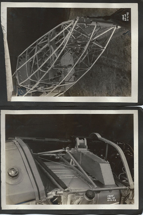
Pages 33-34, snapped November 2, 1928, below, show the aft fuselage including the observer's cockpit and what appears to be a large-format aerial camera just behind the turtledeck bulkhead. The small torque tube running aft in both shots is labeled "Nose up-Nose down." It transfers the pilot's input from the pitch control wheel to the horizontal stabilizer, which moves as a unit to trim the airplane in longitude.
In the bottom photo, the object that looks like a telescope lying parallel to the top fuselage tube is the control stick for the back seater. It can be removed from its mount and inserted into the control fitting so that the back seater can fly the airplane if necessary.
Douglas XO-14, Album Pages 33-34 (Source: Browne)
 |
Below, photographed on November 2, 1928, the top image documents the pilot's cockpit. The control stick is in place, and the worm gear that transfers the force to the elevator trim is visible at the head of the torque tube entering from the rear. The lower wing mounts below the seat.
In the lower photo, the Wright engine is shown in starboard profile with the starting crank inserted in the starter.
Douglas XO-14, Album Pages 35-36 (Source: Browne)
 |
Pages 37-38, below, photographed November 2, 1928 show the pilot (top) and observer cockpits. The handle for adjusting elevator trim is visible just below the gear box, as is the pilot's control stick. Note the "eyebrow" at the top of the firewall (see below). The landing gear strut is visible at lower right, with the attach bolt inserted correctly with the nut facing aft and the head facing the direction of flight. Aircraft are assembled this way with very few exceptions. The fuel tank is visible under the pilot's knees, as are the valves (faucet heads!) to control fuel flow. The observer's cockpit is sparse by comparison.
Douglas XO-14, Album Pages 37-38 (Source: Browne)
 |
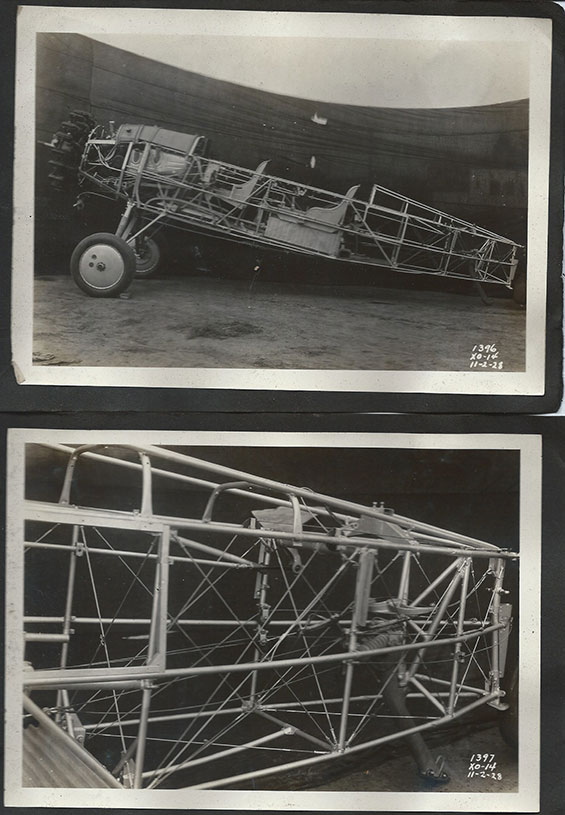
Page 39, below, shows the fuselage in port profile with seats, engine and fuel tanks installed. The lower photograph shows the rear fuselage with tail skid. It shows the coil spring dampener well. Both images were taken November 2,1928.
Douglas XO-14, Album Pages 39-40 (Source: Browne)
 |
The top photograph, below, shows the cockpits from the port side at an oblique angle. The footholds for both the front an rear cockpits are shown. The magneto switch (left, right, both, off) appears as a four-sectored black disk with the switch pointer oriented vertically near what would be the pilot's left knee. In the bottom photo, the lower wing attach fitting is visible as a two-pronged steel fork with bolt holes in the end (look just above the wheel).
Douglas XO-14, Album Pages 41-42 (Source: Browne)
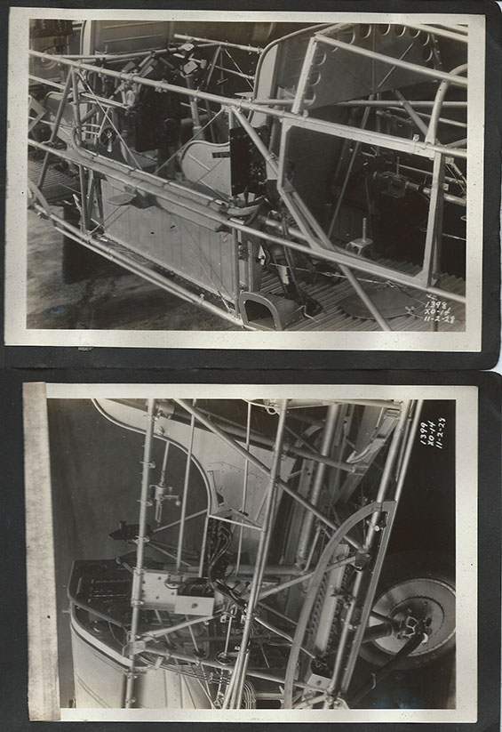 |
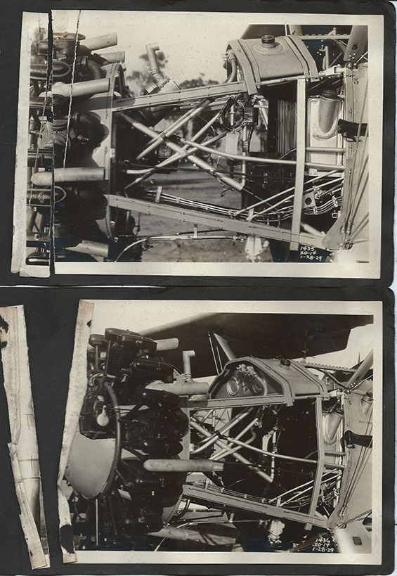
Below, two photographs from November 2, 1928. These show the quality of the aircraft and designer's and mechanics' skills in integrating aircraft systems within the confines of the fuselage frame. The seat and engine controls (slanting diagonally to the left) are clearly visible from the port side in the top photo, as are the filler pipes for fuel and engine oil. The bottom photo, rotated 90° CCW, shows the port side of the engine compartment. The carburetor inlet is at the bottom left of the bottom photo.
Douglas XO-14, Album Pages 43-44 (Source: Browne)
 |
Pages 45-46, below, are interesting in that they show the bottom of the airplane. The top photo shows the steering mechanism which transfers force from the pilot's control stick to both the ailerons and to the elevators. The top image also shows the forward bottom wing attach point in the upper right corner. The bottom photograph shows the carburetor inlet, landing gear struts (protected by canvas sleeves at their compression points, and the wheels, axles and hubcaps, which have filler holes for air.
Douglas XO-14, Album Pages 45-46 (Source: Browne)
 |
Photographed again on November 2, 1928 is the aft fuselage in the top photo showing the tail skid and coil spring shock absorber. The weight bag hanging on the hook prevents the airplane from tipping forward and damaging the engine.
The lower photograph shows the reason for the "eyebrow" pointed out above. It allows for placement of a single machine gun with associated ammunition box mounted on top of the fuel tank ("Cap. 30 U.S. Gals").
Douglas XO-14, Album Pages 47-48 (Source: Browne)
 |
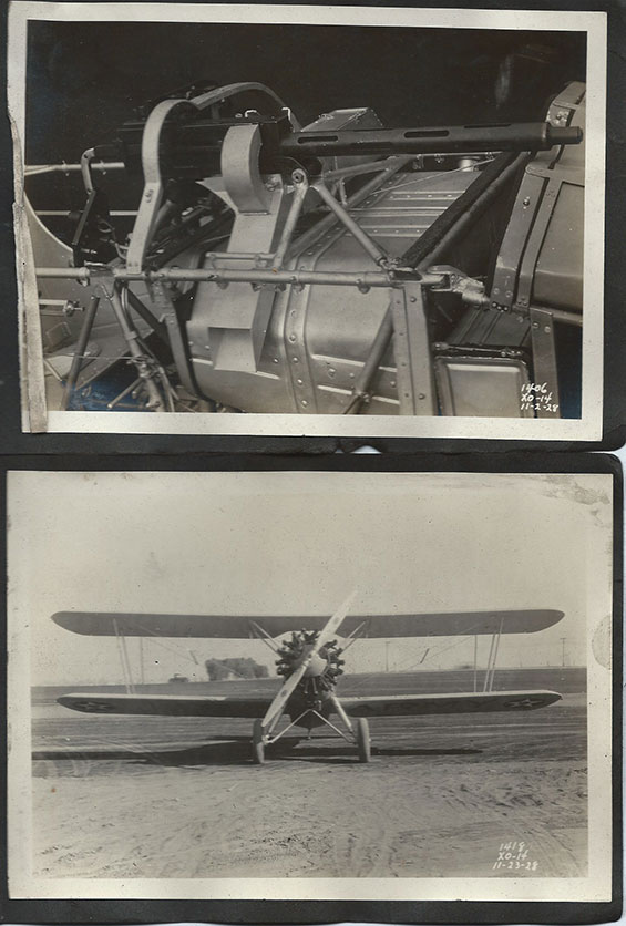
Below we see in the top photograph (November 2, 1928), the geometry of the machine gun placement. Ammunition is fed from the box to the rear, and spent cartridges leave the breech through the chute and out of the airplane.
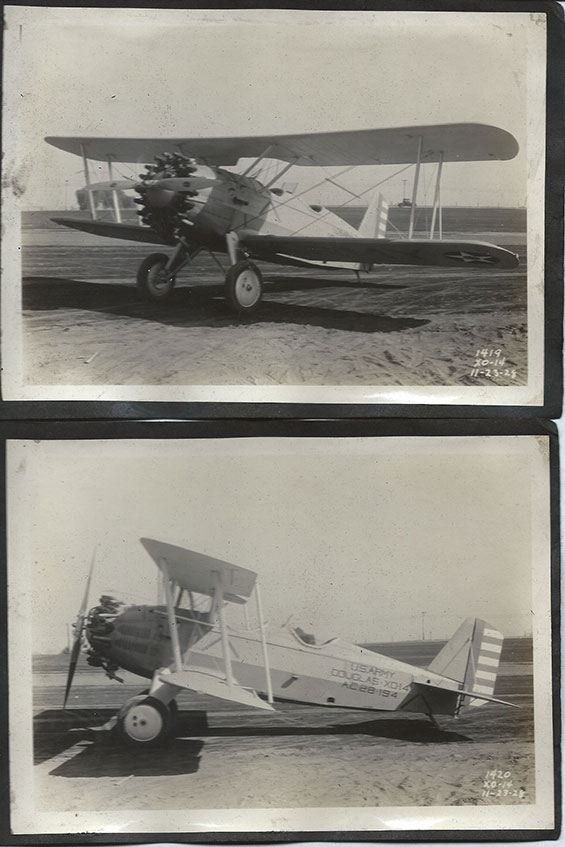
The bottom photograph, snapped on November 23,1928, shows the finished airplane from the front. It took 21 days to cover and paint it. It wears U.S. Army livery.
Douglas XO-14, Album Pages 49-50 (Source: Browne)
 |
The photographs below, also snapped on November 23,1928, show the airplane again in Army livery at an unknown location.
Douglas XO-14, Album Pages 51-52 (Source: Browne)
 |
Below, additional views shot on November 23rd.
Douglas XO-14, Album Pages 53-54 (Source: Browne)
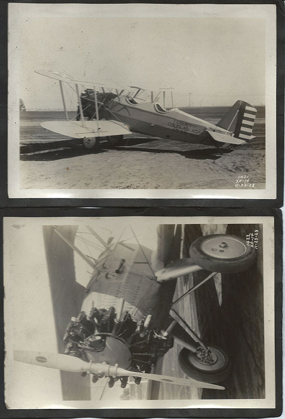 |
Below, from January 28, 1929, are two starboard views of the engine compartment. Note the naked exhaust stacks.
Douglas XO-14, Album Pages 55-56 (Source: Browne)
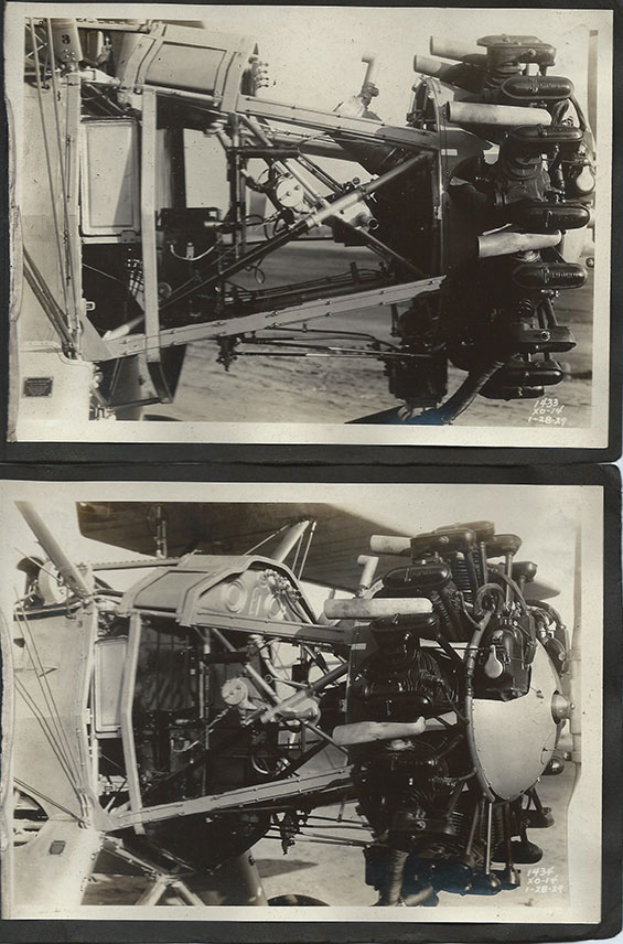 |
Below, from January 28th, are two port views of the engine compartment.
Douglas XO-14, Album Pages 57-58 (Source: Browne)
 |
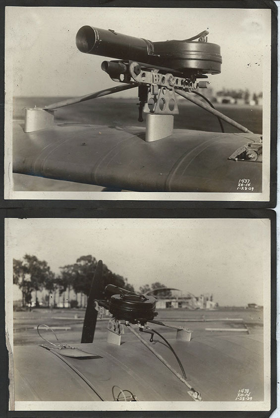
The following two images, pages 59-60, are a puzzle. They show an instrument mounted about midway on top of the wing center section. It could be a camera of some sort (gun camera?). Note what appears to be a winding key on the bottom of the circular manifold in the top photograph. If anyone can identify it, please let me KNOW. Notice, too, the lift cables mentioned with the center section photos above. Location of these photographs is unknown.
Douglas XO-14, Album Pages 59-60 (Source: Browne)
 |
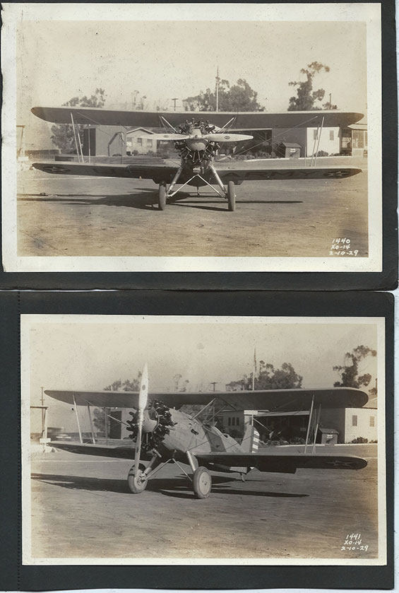
Below, pages 61-62 show two more views of the completed airplane taken February 10, 1929.
Douglas XO-14, Album Pages 61-62 (Source: Browne)
 |
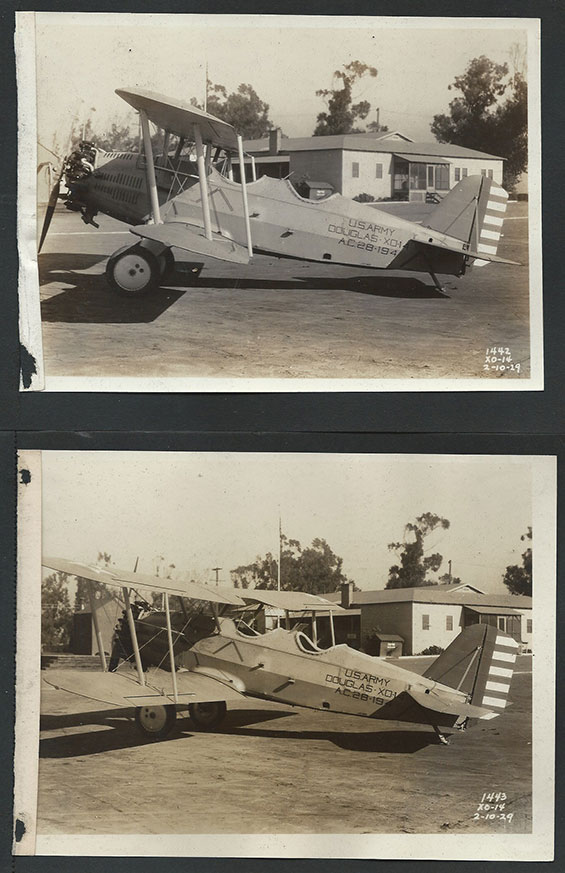
Below are our final photographs, snapped February 10, 1929. Compare the top photograph with the one provided by SDAM (3rd photo down from the top of the page). They are identical.
Douglas XO-14, Album Pages 63-64 (Source: Browne)
 |
These 64 photographs comprise the most thorough graphic documentation of the construction of any airplane on the Davis-Monthan Register Web site. They are even more unique in that they record the construction of a one-of-a-kind airplane. No others of the same model were constructed.
Mr. Browne says about his album, "Picked this up in an estate sale about 10 yrs ago .... purchased for $10."
We both hope you, as site visitors, got $10 worth of enjoyment viewing these photos.
---o0o---
UPLOADED: 09/30/07 REVISED: 07/23/09, 06/27/11, 01/17/15
|